Bus topology is often one of the first network layouts people encounter because it’s simple, visual, and easy to follow. In this guide, you’ll learn how bus topology diagrams are structured, how data moves across the shared backbone, and what the layout looks like in real-world and learning scenarios. We’ll break down key bus topology diagram elements, highlight common design patterns, and point out the limitations you need to account for when working with this topology.
What Is a Bus Topology
A bus topology is a network layout in which all devices are connected to a single continuous cable, known as the backbone. Each device links to this backbone through a tap point, allowing it to send and receive data along the shared line. The backbone serves as the main communication route for the entire network, enabling all connected devices to interact while keeping the physical layout simple and cost-effective.
Physical Bus vs Logical View
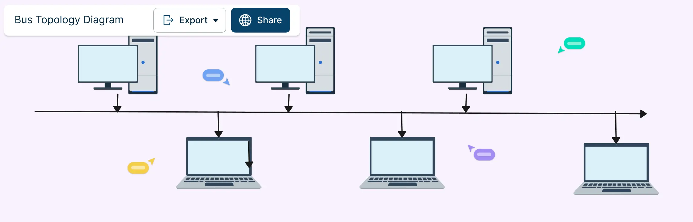
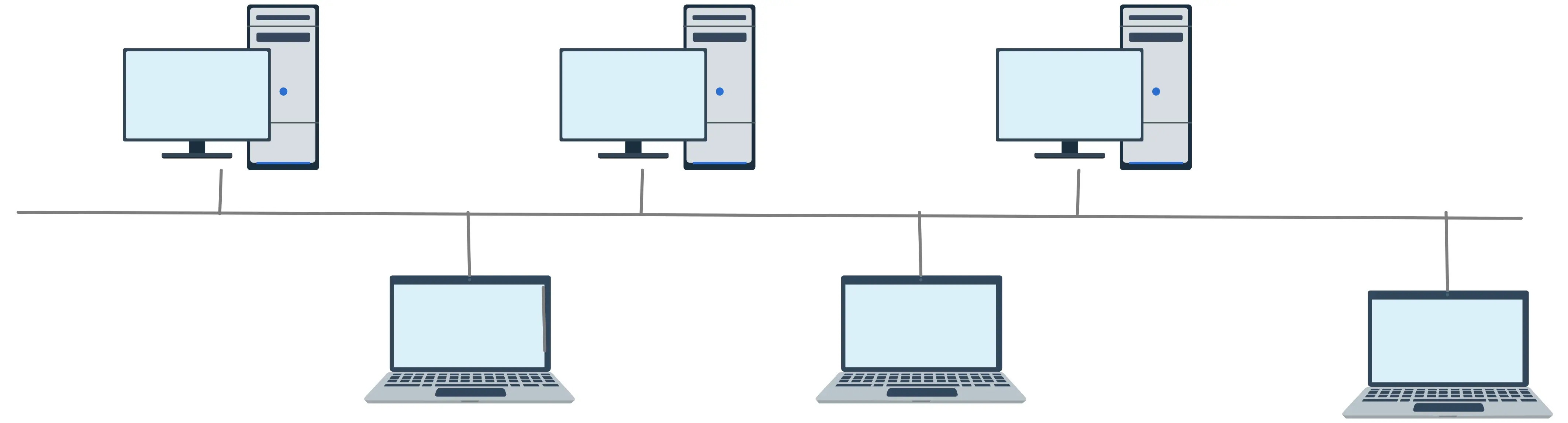
- Physical layout (what you’d draw first): In the physical view, a bus topology diagram shows a single, straight line representing the backbone cable. Along this line, symbols or shapes represent devices (computers, printers, servers). Each device connects to the backbone with a short line called a drop line. At both ends of the backbone, the diagram includes terminators, which are special endpoints that prevent signal reflections and help keep communication stable.
- Logical diagram (how data moves): The logical view focuses on communication behavior rather than exact wiring. Instead of showing physical positions, it illustrates that data travels in both directions along the backbone. Arrows or flow lines indicate how a message propagates from a sending device to all others on the network. Logical diagrams make it easier to explain concepts like collision domains, where more than one device can attempt to send data at the same time.
Tip: Understanding both views makes troubleshooting and diagramming much easier.
How Data Travels on a Shared Medium
Devices send signals onto the backbone when they want to communicate.
The signal travels in both directions and all devices can detect it.
Only the device with the matching address receives and processes the data.
If multiple devices send at the same time, a collision occurs. Networking protocols help detect and manage collisions so communication continues smoothly.
Key point: Bus topology is simple but requires careful management of shared access to keep data flowing efficiently.
Components of Bus Topology
Even though bus topology is simple, it has a few key components that make the network work efficiently. Here’s what you need to know:
- Backbone cable: The backbone is the main cable that connects all devices. It carries all the data traffic and serves as the central communication line for the network.
- Nodes (devices): Nodes are the devices connected to the network — like computers, printers, or servers. Each node attaches to the backbone through a small connector, sharing the same communication line.
- Drop Lines / Taps: Drop lines, or taps, are short connectors linking each device to the backbone. They allow devices to connect without breaking the main cable.
- Terminators: Terminators sit at both ends of the backbone. They absorb signals to prevent them from bouncing back, which keeps communication smooth and avoids errors.
- Transmission medium: This is the physical medium — usually a cable — over which data travels. In classic bus networks, it’s often coaxial or twisted pair cable.
- Collision domain: All devices on the bus share the same collision domain. This means if two devices send data at the same time, signals can collide. Protocols help manage these collisions to maintain smooth communication.
Common Applications of Bus Network Topology
Bus topology may not dominate modern networks, but it’s still widely used where simplicity, low cost, and easy setup are more important than handling heavy traffic. Here are the most common applications:
Small Local Area Networks (LANs): Ideal for small offices or classrooms with a few devices. Minimal cabling and quick setup make bus topology perfect for light-traffic networks.
Legacy Ethernet Networks: Early Ethernet systems like 10BASE2 and 10BASE5 used a shared coaxial backbone. This simple design made networking affordable and easy to deploy.
Automotive Control Systems (CAN Bus): Modern cars use CAN buses to connect electronic control units (ECUs) like engine controllers, braking systems, and sensors. A single backbone reduces wiring complexity and enables efficient communication.
Industrial and Sensor Networks: Some factory automation and IoT sensor systems use a bus-style layout. It links multiple devices along a single line, simplifying installation and supporting predictable data flow.
Testing Labs and Learning Environments: Bus topology is a favorite in networking labs and classrooms, helping students understand shared media, collision domains, and basic networking concepts.
Embedded and Low-Power Systems: Certain microcontroller networks and low-power device clusters use bus layouts to share a communication line efficiently without complex infrastructure.
How to Make Bus Topology Diagrams
A bus topology diagram should visually reflect the actual network design — one shared backbone cable with devices tapping into it. Keeping your diagram neat and annotated makes it easy for learners, technicians, and stakeholders to understand the network’s structure and function at a glance. Here’s how to draw an effective bus topology diagram.
Step 1. Define the backbone
Start by drawing a straight horizontal or vertical line to represent the main communication cable, often called the backbone. This line is the core of your bus network and will connect all devices. Keep it bold and central so it’s easy to follow.
Step 2. Add the nodes (devices)
Place the symbols for each network device — like computers, printers, or servers — near the backbone. Arrange them evenly and clearly. In a typical bus topology, the layout looks like a line with devices branching off it, much like branches from a trunk.
Step 3. Connect devices with drop lines
From each device, draw a short line (drop line) connecting it to the backbone. These vertical or angled connectors show how each node links into the shared cable without crossing lines or creating visual confusion. This mirrors the way real bus networks attach devices to the main line.
Step 4. Include terminators at both ends
At each end of the backbone, place a small symbol or label to represent terminators. Terminators are essential in real bus networks because they absorb signals and prevent reflections that can cause data errors. Showing them visually makes your diagram more accurate.
Step 5. Label clearly
Add clear labels for each device name, IP address, or role (e.g., “Workstation 1,” “Server A”). Good labeling helps readers instantly understand what each node represents. If your diagram will be shared or used for teaching, include a legend or key explaining any symbols you use.
Step 6. Show data direction (optional)
If you want to illustrate how data flows, add small arrows along the backbone to show that signals travel in both directions. This helps viewers grasp the logical behavior of a bus network, where messages broadcast outward from the sending device.
Step 7. Review for simplicity and readability
Before finalizing your diagram, make sure it’s not cluttered. Keep shapes aligned, use consistent visual styles, and group related elements. A clear layout makes technical concepts more approachable and easier to interpret.
Advantages and Disadvantages of the Bus Topology Diagram
Bus topology is simple and easy to understand, making it a popular choice for small networks and learning environments. However, its shared backbone design comes with trade-offs that are important to consider. The table below summarizes the main advantages and disadvantages:
| Advantages | Disadvantages |
| Simple and cost-effective — requires less cabling and hardware | Limited scalability — performance drops as more devices are added |
| Easy to set up — quick installation for small networks | Single point of failure — if the backbone fails, the network goes down |
| Easy to extend — adding devices is straightforward | Collisions are common — simultaneous transmissions can interfere |
| Ideal for small networks with low traffic | Troubleshooting can be challenging, especially in long networks |
| Clear visualization — linear layout is easy to represent in diagrams | Limited speed under high traffic or many devices |
| Low cost for hardware and maintenance | Security concerns — shared medium can be more vulnerable to unauthorized access |
Bus Network Topology vs Other Network Diagram Topologies
Understanding how bus topology compares to other network layouts helps you choose the right design for your needs. Each topology has its strengths and weaknesses, and visualizing them side by side makes it easier to see which setup works best for your network size, traffic, and reliability requirements.
| Topology | Advantages | Disadvantages | Best Use Cases |
| Bus Topology | Simple and cost-effective; easy to install; minimal cabling | Single point of failure; limited scalability; collisions can occur | Small networks, labs, legacy systems |
| Star Topology | Centralized management; easy to troubleshoot; failures in one device don’t affect others | Requires more cabling; central hub failure can disrupt network | Offices, schools, modern LANs |
| Ring Topology | Data travels in one direction reducing collisions; predictable performance | A single node failure can affect the network; difficult to add/remove devices | Token Ring networks, specialized industrial setups |
| Mesh Topology | High reliability; fault-tolerant; multiple paths for data | Expensive; complex to set up; requires lots of cabling | Large enterprise networks, critical systems |
| Tree Topology | Hierarchical; combines star and bus benefits; scalable | Backbone failure can affect branches; more cabling needed | Corporate networks, university campuses |
| Hybrid Topology | Flexible; combines advantages of multiple topologies | Complex design; can be costly | Large networks with mixed requirements |
Bus Topology Diagram Examples
Bus Topology


Bus Topology Network Diagram

Bus Topology Example

Basic Bus Topology

Bus Topology DIagram

FAQs About Bus Topology
When should I use a bus topology diagram?
What are real-world examples of bus network topology?
What is the best free tool to create a bus topology diagram?
What are terminators, and why are they important?
Can a bus topology network be expanded?
Is bus network topology reliable for modern networks?
What is the difference between bus and star topology?