Designing and managing a network can quickly become overwhelming, cables everywhere, unclear data paths, and confusing layouts can leave even experienced IT teams frustrated. That’s why understanding the difference between logical topology vs physical topology is essential. In this guide, we’ll break down physical and logical topologies, explain how they differ, and show you how to create clear, accurate diagrams that save time, reduce errors, and make collaboration effortless. Plus, you’ll discover ready-to-use templates that let you map networks visually without the stress of starting from scratch.
What Is Physical Topology?
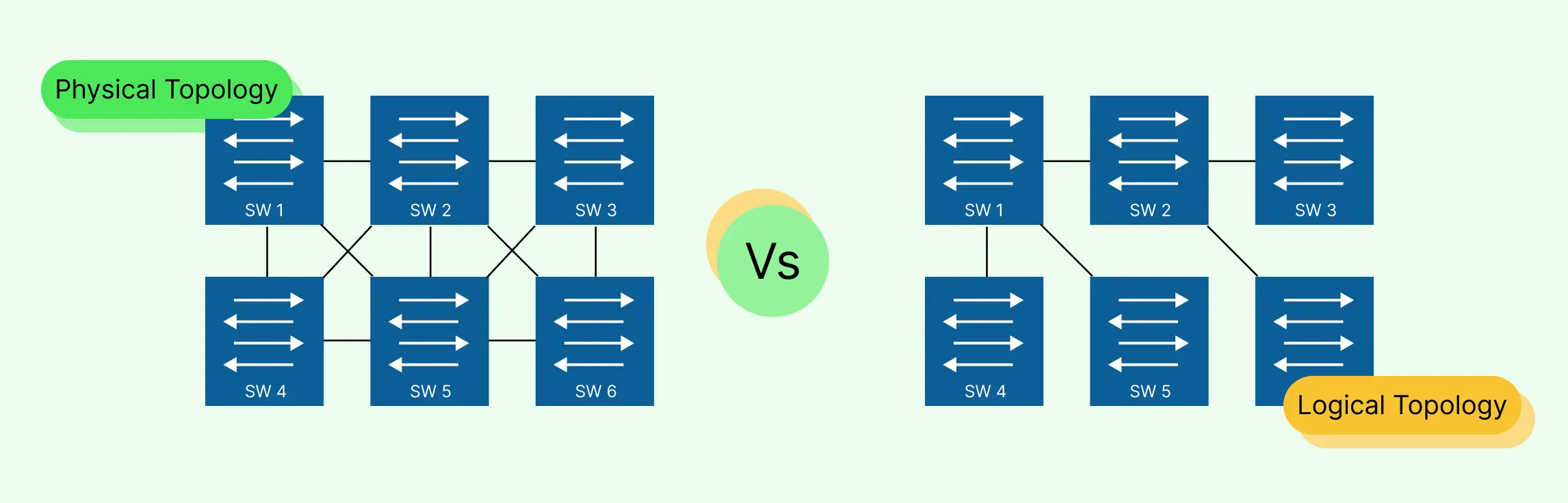
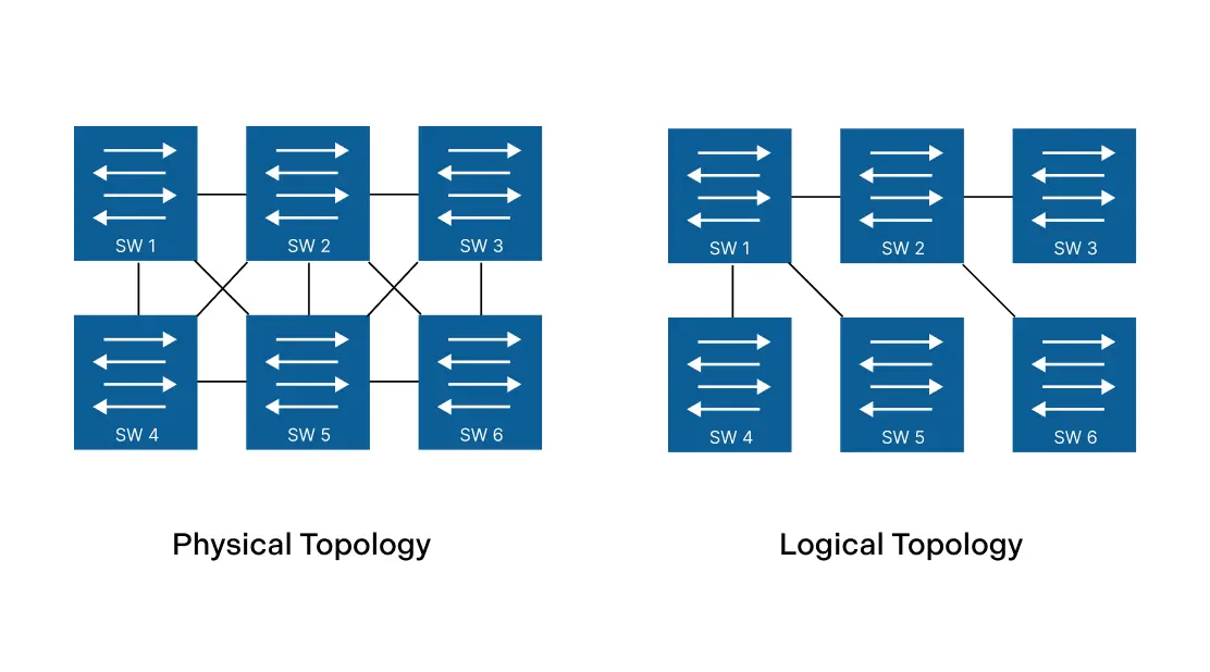
Physical topology refers to the actual layout of devices, cables, and network hardware in a network. Think of it as the “map” of how your network’s computers, routers, switches, and other devices are physically connected. Unlike logical topology, which shows how data flows, physical topology is all about the tangible, visible connections that keep your network running smoothly.
Common Types of Physical Topologies
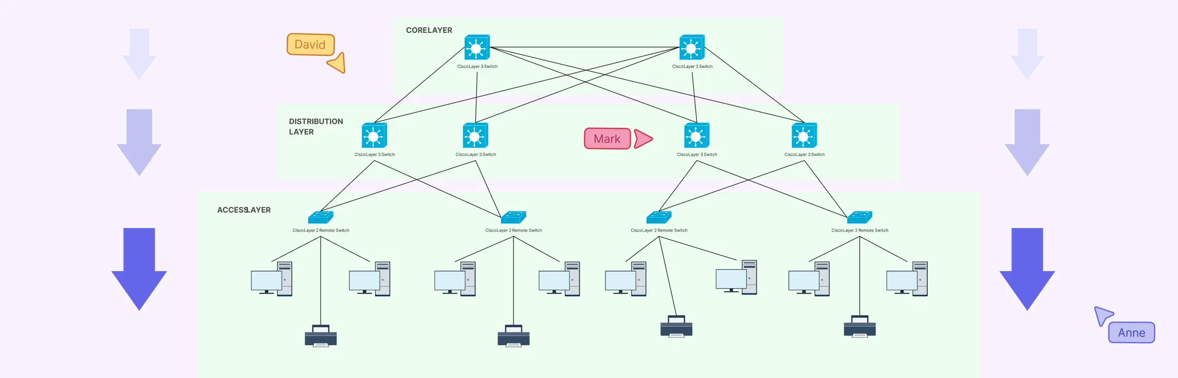
- Star Topology: All devices connect to a central hub or switch. Ideal for small-to-medium networks, it’s easy to manage and troubleshoot.
- Bus Topology: Devices are connected along a single cable. Simple and cost-effective, but a single failure can bring down the entire network.
- Ring Topology: Devices form a circular connection where data travels in one direction. It reduces collisions but can be challenging to expand.
- Hybrid Topology: A mix of two or more topologies, offering flexibility to scale and adapt based on network needs.
Advantages of Physical Topology
Understanding physical topology gives network teams a strong foundation for building reliable and scalable systems. When designed well, it offers several practical advantages:
- Improved Network Reliability: Certain physical topologies, such as mesh networks, are built with redundancy in mind. If one cable or device fails, traffic can be rerouted through another path, helping the network stay operational instead of going completely offline.
- Clear, Visual Network Structure: Physical topology provides a tangible view of how devices are connected. This makes it easier for teams to understand the network layout, identify faulty hardware, and perform maintenance with confidence. When everything is clearly mapped out, troubleshooting becomes faster and far less stressful.
- Easier Scalability in Modern Networks: Some physical topologies, especially star topology, make it simple to expand a network. New devices can be added without redesigning the entire structure, supporting long-term growth and smoother hardware planning.
Disadvantages of Physical Topology
While physical topology is essential for network design, it also comes with limitations that teams must plan for:
- Susceptibility to Physical Damage: Because physical topology depends on real-world cables and hardware, it is vulnerable to damage from wear and tear, accidents, or environmental factors. A single broken cable can disrupt connectivity if redundancy is not in place.
- Limited Flexibility for Changes: Modifying a physical network layout often requires unplugging devices, rerouting cables, and reconfiguring hardware. This can be time-consuming and disruptive, especially in large or complex environments.
- Higher Setup and Maintenance Costs: Building certain physical topologies can be expensive. Extensive cabling, specialized equipment, and backup hardware increase both initial setup costs and long-term maintenance expenses.
What Is Logical Topology?
Logical topology describes how data moves across a network, regardless of the physical connections between devices. While physical topology shows the layout of cables and hardware, logical topology focuses on the flow of information; how data travels from one device to another, which devices communicate with each other, and how traffic is managed across the network.
Advantages of Logical Topology
Logical topology plays a critical role in how modern networks operate behind the scenes. It offers powerful benefits that support speed, adaptability, and smarter network management:
- Greater Flexibility in Network Design: Logical topology allows network engineers to design data flow based on business and technical needs rather than physical constraints. This means networks can be optimized logically without rewiring hardware, making it ideal for cloud and virtual environments.
- More Efficient Use of Network Resources: By defining smarter data paths and routing rules, logical topology helps networks use bandwidth and infrastructure more efficiently. Well-designed logical connections reduce congestion and improve overall network performance.
- Easier Updates and Improvements: Making changes to a logical topology is typically faster and less disruptive than modifying physical cabling. Teams can reconfigure traffic flows, update routing policies, or optimize performance without taking the entire network offline.
Disadvantages of Logical Topology
Despite its advantages, logical topology also introduces challenges that teams must manage carefully:
- Increased Technical Complexity: Logical topology relies on advanced configurations, protocols, and routing rules. Without proper expertise, networks can become difficult to manage and troubleshoot effectively.
- Dependence on Network Protocols: Logical topology functions correctly only when protocols and configurations are working as intended. Errors in routing tables or protocol settings can disrupt data flow across the network.
- Potential Security Vulnerabilities: Misconfigured logical connections or routing rules can expose networks to security risks. Poorly managed logical topology may create entry points for unauthorized access or data breaches.
Key Differences Between Physical and Logical Topology
When it comes to network design, understanding the difference between physical and logical topology is essential. While physical topology shows how devices are physically connected, logical topology focuses on data flow and traffic. The table below makes the physical vs logical topology differences clear at a glance:
| Feature | Physical Topology | Logical Topology |
| Structure | Shows the actual layout of devices and cables. | Shows how data flows between devices, independent of physical connections. |
| Visualization | Map of hardware, including switches, routers, and cables. | Diagram of network traffic, logical connections, and virtual paths. |
| Use Cases | Hardware planning, cabling design, and maintenance. | Routing, software configuration, network optimization, virtual networks. |
| Scalability | Changes require physical adjustments (new cables, devices). | Can adapt logically without changing physical layout, ideal for virtual or cloud networks. |
| Troubleshooting | Helps locate hardware failures or connectivity issues. | Helps identify data flow bottlenecks, misrouted traffic, or configuration errors. |
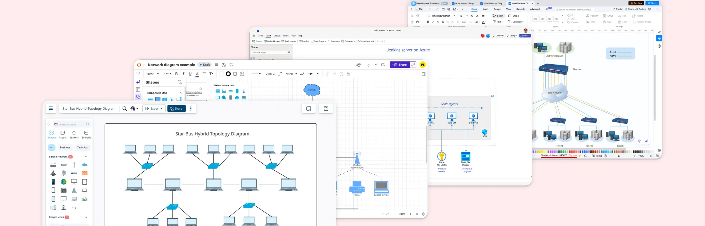
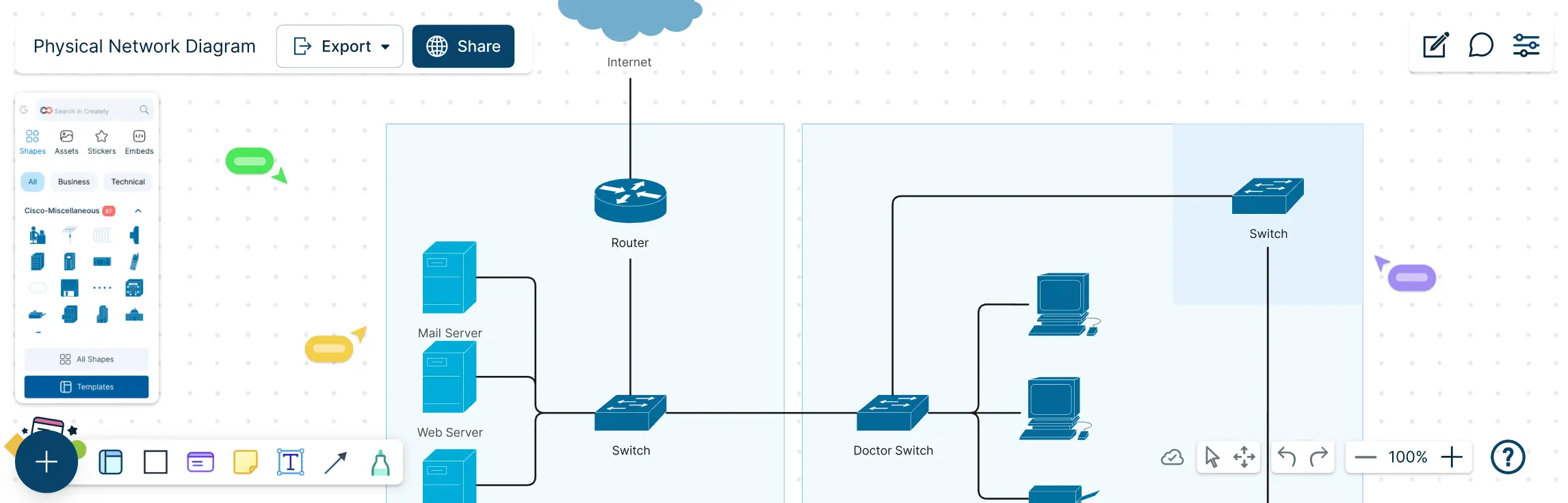
Free Templates to Visualize Physical and Logical Topologies


Best Practices for Drawing Physical and Logical Topologies
Creating network diagrams that are both accurate and easy to understand doesn’t have to be stressful. By following a few best practices, you can save time, reduce errors, and make network management a breeze.
1. Use Clear Labels, Consistent Symbols, and Colors
- Label every device, switch, router, and connection clearly.
- Stick to consistent symbols and colors to represent different types of devices or connections.
- Helps anyone viewing the diagram understand the network at a glance.
2. Separate Physical Layout from Logical Flow
- Keep physical topology diagrams and logical topology diagrams distinct.
- Avoid clutter by showing hardware connections in one diagram, and data flow in another.
- Makes troubleshooting and planning much easier.
3. Collaborate in Real-Time
- Work with your team using real-time collaborative tools like Creately.
- Instantly share updates, get feedback, and avoid miscommunication.
- Perfect for distributed teams or hybrid work environments.
4. Spend Less Time Stressing, More Time Solving
- Good practices don’t just improve clarity, they reduce frustration.
- With organized, visually clear diagrams, you can focus on solving network challenges instead of untangling messy maps.
- The goal is to make network planning fast, efficient, and even enjoyable.
Understanding the difference between physical and logical topology is more than just theory; it’s a practical step toward faster troubleshooting, better network planning, and smoother team collaboration. By applying the best practices outlined in this guide and using tools like Creately’s free templates, you can create network diagrams that are both clear and actionable, empowering your team to work efficiently. Start visualizing your networks the smart way, get started with Creately for free today and see how easy it is to bring your network layouts to life.
Helpful Resources
Learn how to draw a network diagram step by step, from planning what to include to laying out components clearly and choosing the right symbols.
Discover key bus topology diagram elements, highlight common design patterns, and point out the limitations you need to account for when working with this topology.
Understand how to approach Cisco network topology diagrams with confidence and create visuals that are practical, accurate, and easy to understand.
Learn how to create a home network setup diagram step by step, understand common layouts, follow practical best practices, and use free templates to map your setup.
Discover how to create a wide area network diagram step by step, understand key components, WAN examples, and follow proven best practices.
Everything you need to know about LANs, from the basics and key components to network types, advantages, and best practices.
Discover what a logical network diagram is, how it differs from a physical network diagram, why it’s useful, and how to create one.